
Ladder Logic Troubleshooting: Common Faults & How to Fix Them
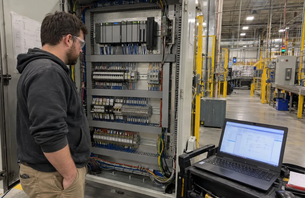
Ladder logic troubleshooting helps maintenance teams identify why a PLC-controlled machine is not operating as expected. By tracing input conditions, program instructions, and output commands, technicians can determine whether a fault originates in the PLC program, control hardware, or field wiring.
For plant and maintenance managers, a consistent troubleshooting process helps reduce unnecessary downtime, prevent guesswork, and restore equipment safely. This guide covers common ladder logic faults, how to diagnose them, and the skills technicians need to resolve control-system problems reliably.
PLC and ladder logic training for your team can help build the electrical and control-system knowledge needed for this work.
How Ladder Logic Works in PLC Troubleshooting
Ladder logic is a graphical programming language that uses symbols resembling electrical relay diagrams to represent control operations. Each horizontal line, called a rung, contains instructions that determine when specific actions can occur.
A typical PLC control system has three main components:
-
Inputs: Signals from start buttons, limit switches, proximity sensors, and other field devices.
-
Program logic: Instructions that evaluate input states, internal bits, timers, counters, and operating conditions.
-
Outputs: Commands that control motor starters, solenoids, indicator lights, and other equipment.
For example, a conveyor motor may start when an operator presses the Start button and all required permissives are satisfied. The PLC evaluates the programmed conditions and issues the command to start the motor.
Understanding the PLC Scan Cycle
Many PLCs repeatedly execute program logic, updating inputs and outputs according to the controller’s scan sequence and configuration. Some use periodic tasks or asynchronous I/O updates, so execution behavior varies by platform.
When troubleshooting, technicians need to understand how instruction execution affects program behavior. They should also distinguish between a ladder contact instruction and a physical electrical contact. A normally open ladder contact instruction evaluates whether its associated Boolean condition is true; it does not necessarily indicate that a physical switch is open.
For more on processor faults, communication problems, and PLC hardware diagnosis, see our PLC Troubleshooting: A Step-by-Step Guide for Maintenance Teams.
Common Ladder Logic Faults and How to Fix Them
Ladder logic faults can stem from incorrect instructions, conflicting conditions, unexpected data values, or faulty field devices. Recognizing common symptoms helps maintenance teams identify the likely cause before changing the program or replacing components.
1. Outputs That Remain On Unexpectedly
A motor may continue running after an operator presses Stop because of a retained latch, incorrect stop logic, or multiple instructions writing to the same output tag.
How to troubleshoot: Trace the output’s controlling logic and check all instructions that write to the associated tag. Determine whether the PLC command remains on or the physical output stays energized after the command turns off.
For Rockwell Automation controllers, the cross-reference tool can help identify instructions that read or modify a tag.
2. Missing Seal-In Conditions
A motor that runs only while the operator holds the Start button may have a missing seal-in branch or an incorrect holding condition.
How to troubleshoot: Check the parallel holding branch and confirm that it references the correct run condition. Verify that Stop commands and required interlocks can interrupt the run command as intended.
3. Unsatisfied Conditions and Incorrect Interlocks
A machine may refuse to start because a required permissive, such as a minimum tank level or motor protection signal, remains false. The condition may reflect a legitimate process state or a faulty input.
How to troubleshoot: Identify the first unsatisfied condition in the affected rung. Compare the PLC input value with the actual field-device state. Never bypass an interlock simply to force the machine to operate.
4. Execution-Order and Timing Problems
A program may behave unexpectedly when multiple instructions write to the same tag or when task timing affects how data is updated. Timer, counter, and one-shot logic can also produce unexpected results when configured incorrectly.
How to troubleshoot: Review the affected tag’s references, instruction sequence, and task configuration. Use available trends or diagnostic logs to determine when values change, then correct the underlying logic or timing dependency.
5. Input and Output Hardware Faults
A faulty sensor, damaged wiring, failed output module, or missing field power can produce symptoms that resemble a programming error. For example, a conveyor may stop advancing because a proximity sensor never registers the expected position.
How to troubleshoot: Compare the PLC’s input and output status with the actual field conditions. Check module diagnostics and have qualified personnel inspect the relevant electrical circuit under approved safety procedures.
Common Symptoms and What to Check
| Machine Symptom | Possible Cause | What to Verify |
|---|---|---|
| Motor stops when Start is released | Missing seal-in condition | Holding branch and run logic |
| Output remains commanded on | Retained latch or conflicting instructions | Reset conditions and tag references |
| Rung never becomes true | Unsatisfied permissive or failed sensor | Input status and field-device operation |
| Output changes unexpectedly | Multiple writes or timing dependency | Tag references and program execution |
| PLC output is on, but equipment does not respond | Wiring, output module, or power fault | Module diagnostics and field circuit |
| Analog reading is incorrect | Sensor, scaling, or configuration issue | Raw value, signal range, and scaling |
Verify the suspected cause before replacing components or modifying the program. Changes to control logic should follow the facility’s approved review, testing, and change-control procedures.
A Step-by-Step Ladder Logic Troubleshooting Process
A consistent troubleshooting process helps maintenance teams identify the cause of PLC faults, avoid unnecessary component replacements, and return equipment to service safely. Plant and maintenance managers can use the following steps to establish a repeatable approach across their teams.
Step 1: Confirm the Symptom and Establish Safe Conditions
Have technicians document the machine behavior, relevant alarms, operating conditions, and events preceding the failure. Establish whether the initial investigation can use nonintrusive monitoring or requires physical inspection and testing.
For covered servicing and maintenance activities, follow the facility’s hazardous-energy control procedures and applicable OSHA lockout/tagout requirements. A stopped machine or inactive PLC output does not confirm that hazardous energy has been isolated.
Step 2: Check PLC Status and Diagnostics
Check the controller status, I/O module diagnostics, communication connections, and active fault messages before investigating individual rungs. These checks can reveal controller, module, or communication problems that do not require program changes.
Step 3: Locate the Relevant Logic
Use authorized programming software to find the rung or routine associated with the affected device or sequence. Review rung descriptions, I/O addresses, and related logic to confirm that you are investigating the correct part of the program.
Step 4: Trace Input Conditions and Program Logic
Monitor the relevant instructions and compare their states with the expected operating conditions. If a motor-start rung remains false, for example, identify the condition preventing it from becoming true.
Trace internal bits to the instructions that control them, and check related timers, counters, permissives, and reset conditions. Remember that online monitoring may not capture brief signal changes or every intermediate execution state.
Step 5: Verify Field Signals and Hardware
If PLC values do not match actual machine conditions, investigate the associated sensors, wiring, I/O modules, and power supplies. A limit switch may report the wrong state because of a failed device or wiring fault, even when the program logic is correct.
Electrical testing must follow applicable safety procedures. OSHA’s electrical safety-related work practices address requirements for working on or near electrical parts, including deenergization and employee qualifications.
Step 6: Correct the Cause and Verify the Repair
Choose a corrective action based on the confirmed fault. This may involve repairing wiring, replacing a failed sensor, correcting a configuration, or revising the PLC program.
Require program changes to follow established change-control procedures, including backups, appropriate review, testing, and documentation. Before returning equipment to production, verify the affected operating sequence, required interlocks, and equipment response under approved operating conditions.
Document the fault, root cause, corrective action, and verification results. Maintenance managers can use these records to identify recurring problems, improve troubleshooting procedures, and target future training.
Reading Electrical Schematics and Control Circuits
Your technicians need to understand how PLC logic connects to the electrical circuits and devices controlling your equipment. Electrical schematics, wiring diagrams, and terminal schedules provide the information they need to interpret PLC addresses in the context of the installed control system.
For example, a pressure switch referenced in a ladder logic rung can be traced through the electrical drawings to identify its terminals, wiring connections, and place in the control circuit. This knowledge helps technicians understand how the PLC program relates to the equipment they maintain.
For plant and maintenance managers, developing electrical print-reading skills across the team supports more consistent maintenance practices and reduces reliance on a few technicians who know the equipment best.
ITC Learning’s electrical print reading course covers schematic symbols, control components, and wiring diagrams. For more on relay circuits, motor starters, and field wiring, see our guide to control circuit troubleshooting.
What Individual Technicians Should Learn About Ladder Logic
For individual technicians, learn to trace ladder logic rung by rung, check whether input conditions are met, and identify how instructions affect PLC outputs. Focus on recognizing common logic problems, including missing seal-in conditions, unsatisfied interlocks, and timer or counter instructions that prevent a machine from operating as expected.
Practice tracing faults in a simulated PLC program. Identify the rung involved, determine which condition is preventing the expected operation, and explain what needs to be checked before correcting. Simulation and supervised exercises help you build these skills without experimenting on operating production equipment.
Improving Equipment Reliability Through Better Ladder Logic Troubleshooting
Effective ladder logic troubleshooting means identifying the root cause before making changes to a PLC program. When you oversee maintenance, consistent diagnostic practices help your team address control-system faults accurately and reduce unnecessary downtime.
Explore PLC and ladder logic training for your team to support your technicians’ electrical and control-system skills.
Why Organizations Choose ITC Learning
ITC Learning training capabilities include:
-
50+ years developing skilled-trades training.
-
1M+ learners trained across technical and industrial skills.
-
175+ courses and 450+ lessons covering electrical, mechanical, and other skilled-trades subjects.
-
SCORM-compliant training delivered through the ITC Learning LMS or an existing compatible learning management system.
-
Training available in English and Spanish to support workforce needs.
-
Support for manufacturers, industrial employers, educational institutions, workforce development programs, apprenticeships, and Career and Technical Education (CTE) partnerships.
These resources help organizations establish structured learning pathways while supporting both experienced maintenance personnel and developing technicians.